

Plumbing Equipments /
131.19 KDT STEEL HYDRAULIC SEPARATOR
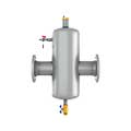
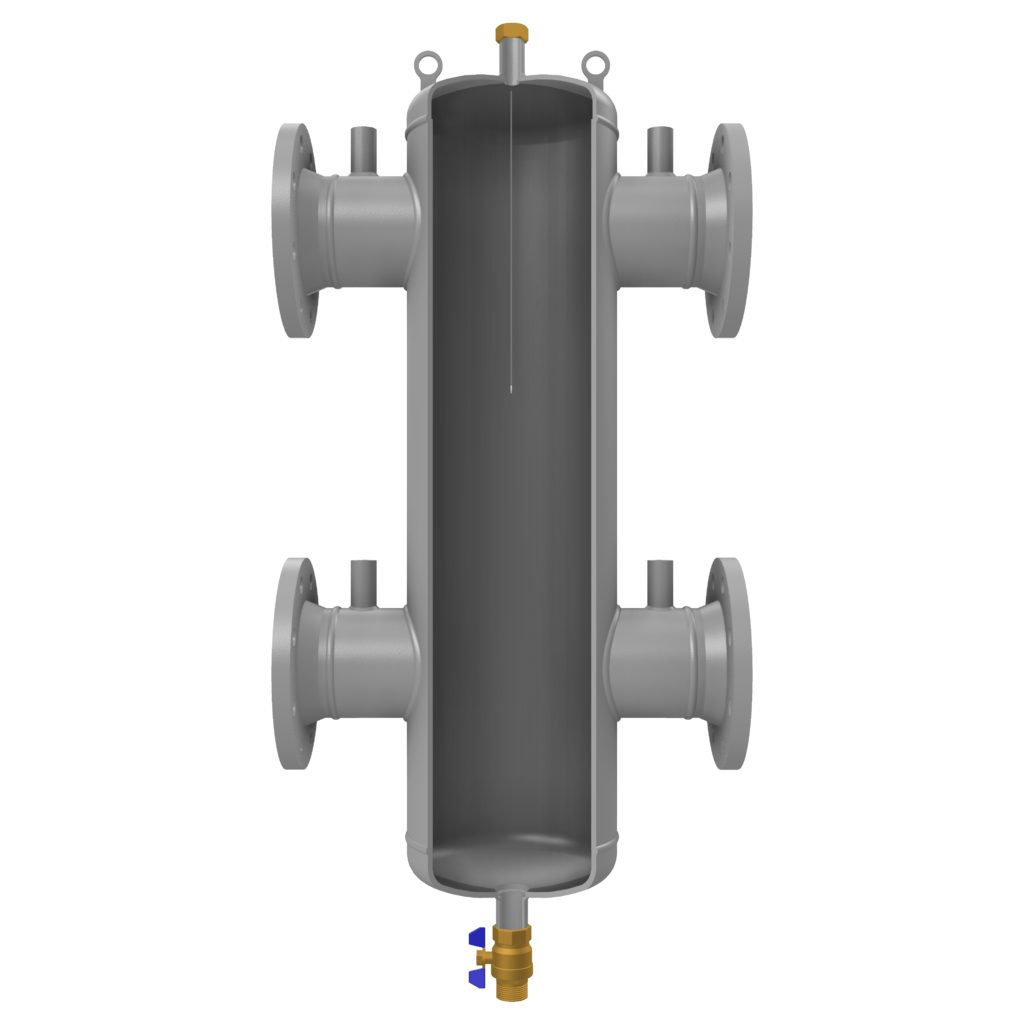
KDT Steel Hydraulic Separator
The Steel Hydraulic Separator is a device which makes the primary and secondary circuits connected to it independently. It can be used in hot or chilled water systems. The Steel Hydraulic Separators are supplied with air vent to permit automatic discharge of the air in the circuit and a drain valve for removing any impurities accumulated in the bottom of the unit. The hydraulic separator should
be sized according to the maximum flow rate value of the primary or secondary circuit, whichever is the greatest.
SPECIFICATIONS / USAGE AREAS
• In systems where primary and secondary hydraulic circuits should be separated hydraulically from each other.
• When circulation capacity needs are different in primary and secondary circuits
• In systems where more than one energy sources (cascade system) are used
• In systems where several pumps and heating circuits are present
• In systems where pressure balancing is needed
• In systems where energy supply and/or energy demand are not constant
• Percentage of glycol in the heating system is maximum 50%.
Features
Maximum Operating Temperature
110 °C
Maximum Operating Pressure
1000 kPa (10 bar)
Connection Sizes / Pressure Class
Flanged Connection: DN50-DN150 / PN16
Welded Connection: 60,3 mm-168,3 mm
(Please contact for products between DN200- DN600)
Filter Material
Perforated Turbulator
Outer Surface Protection Paint
Electrostatic Powder Paint
Manufactured in accordance with 2014/68/EU Pressure Equipment Directive and EN 13445-3 Standards.
Flanged Steel Hydraulic Separator
| Code | 131.19.16.1 | 131.19.17.1 | 131.19.18.1 | 131.19.19.1 | 131.19.20.1 | 131.19.21.1 | |
| A | mm | DN50 | DN65 | DN80 | DN100 | DN125 | DN150 |
| 2” | 2½” | 3” | 4” | 5” | 6” | ||
| B | mm | 450 | 450 | 470 | 470 | 635 | 635 |
| C | mm | 3/4″ | 3/4″ | 3/4″ | 3/4″ | 3/4″ | 3/4″ |
| D | mm | 265 | 265 | 285 | 285 | 300 | 300 |
| E | mm | 795 | 795 | 940 | 940 | 1160 | 1160 |
| F | mm | 1” | 1” | 1” | 1” | 1” | 1” |
| G | mm | 330 | 330 | 450 | 450 | 560 | 560 |
| H | mm | 1/2″ | 1/2″ | 1/2″ | 1/2″ | 1/2″ | 1/2″ |
| Weight | kg | 24 | 27 | 37 | 40 | 65 | 75 |
| Volume | lt | 14 | 14 | 28 | 28 | 78 | 78 |
| Kv | m3/h | 76 | 125 | 172 | 304 | 451 | 663 |
| Min.-Max. Flow rate | m3/h | 5-15 | 10-22 | 15-30 | 25-60 | 35-83 | 55-125 |
Kv = Q / √ΔP… Q = Water flow rate (m³ / h)
ΔP = Pressure loss on the product (bar)
Welded Steel Hydraulic Separator
| Code | 131.19.16.2 | 131.19.17.2 | 131.19.18.2 | 131.19.19.2 | 131.19.20.2 | 131.19.21.2 | |
| A | mm | DN50 | DN65 | DN80 | DN100 | DN125 | DN150 |
| 60,3 | 76,1 | 88,9 | 114,3 | 139,7 | 168,3 | ||
| B | mm | 360 | 360 | 370 | 370 | 580 | 580 |
| C | mm | 3/4” | 3/4” | 3/4” | 3/4” | 3/4” | 3/4” |
| D | mm | 265 | 265 | 285 | 285 | 300 | 300 |
| E | mm | 795 | 795 | 940 | 940 | 1160 | 1160 |
| F | mm | 1” | 1” | 1” | 1” | 1” | 1” |
| G | mm | 330 | 330 | 450 | 450 | 560 | 560 |
| H | mm | 1/2″ | 1/2″ | 1/2″ | 1/2″ | 1/2″ | 1/2″ |
| Weight | kg | 14 | 15 | 21 | 22 | 40 | 45 |
| Volume | lt | 14 | 14 | 28 | 28 | 78 | 78 |
| Kv | m3/h | 76 | 125 | 172 | 304 | 451 | 663 |
| Min.-Max. Flow rate | m3/h | 5-15 | 10-22 | 15-30 | 25-60 | 35-83 | 55-125 |
Kv = Q / √ΔP… Q = Water flow rate (m³ / h)
ΔP = Pressure loss on the product (bar)
KODSAN reserves the right to change the product specifications, technical information and installation diagrams without any notifications.
All information written on this page can not be copied or used without permission of KODSAN. Kodsan can not be held responsible if any of the technical information and schemes are considered exemplary by third parties.