Water Heaters & Storage Tanks /
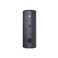
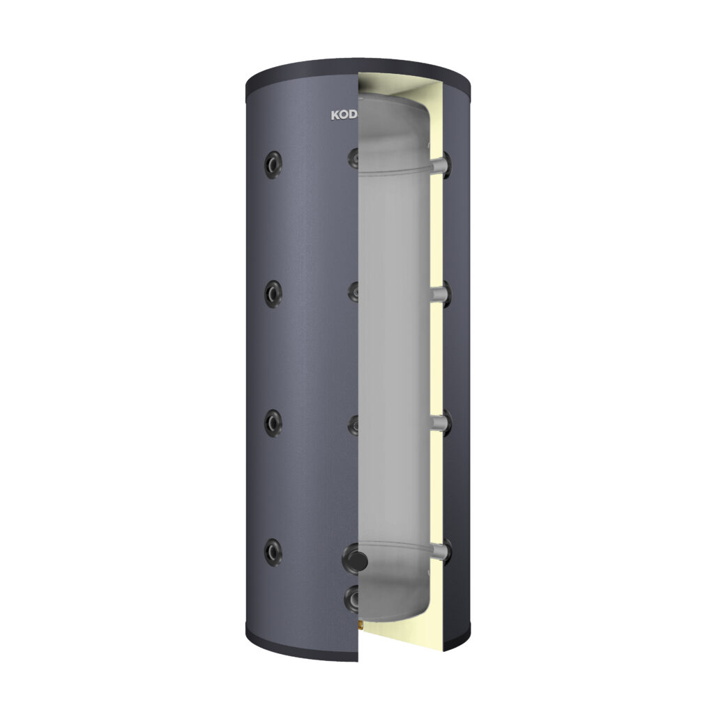
101.13 KBT-B BUFFER TANK
Features
Volume
100L – 5000L
Domestic Hot Water Maximum Operating Temperature
95°C
Domestic Hot Water Maximum Operating Pressure
6 Bar
Manufactured in accordance with 2014/68/EU Pressure Equipment Directive, TS EN 13445-3 and TS EN 12897 Standards.
Insulation and Equipments
| 101.13 Buffer Tank | 100L-300L | 500L | 800L-1000L | 1500L-2000L | 2500L-3000L | 4000L-5000L | |
| Insulation | PU- 42kg/m3 HCFC-free polyurethane in accordance with the 814/2013 EU ErP Comission Regulations and TS EN 12897 Standards | STD/50 mm | STD/50 mm | x | x | x | x |
| Soft PU- 15 kg/m3 soft polyurethane | x | x | STD/80 mm | STD/80 mm | STD/80 mm | STD/80 mm | |
| Soft PU- 26 kg/m3 flame retardant soft polyurethane | x | x | OPS/80 mm | OPS/80 mm | OPS/80 mm | OPS/80 mm | |
| Izomax- 50kg/m3 insulation with d0 fire class as well as with BL-S3 compatible with the ErP regulations following the 814/2013 EU Comission Regulations and TS EN 12897 Standards | x | x | OPS/80 mm | OPS/80 mm OPS/100 mm |
OPS/80 mm | OPS/80 mm | |
| Coating | Blueshell- Recyclable polyethylene cover that provides heat-saving | STD | STD | x | x | x | x |
| Vinleks- Artificial Leather | x | x | STD | STD | STD | STD | |
| Izoqua- Waterproof PVC unit which is suitable for exterior usage. (Offered optionally with the izomax insulation application) | x | x | OPS | OPS | OPS | OPS | |
| Equipment | Thermometer (0°C- 120°C) | OPS/Ø63 | OPS/Ø63 | OPS/Ø100 | OPS/Ø100 | OPS/Ø100 | OPS/Ø100 |
| Steel Sensor Tube | OPS/Ø9 mm 3 pieces |
OPS/Ø9 mm 3 pieces |
OPS/Ø9 mm 3 pieces |
OPS/Ø9 mm 3 pieces |
OPS/Ø9 mm 3 pieces |
OPS/Ø9 mm 3 pieces |
|
| Cleaning & Control Flange | x | x | x | x | x | x | |
| Electric Heater | x | OPS/1½” | OPS/2″ | OPS/2″ | OPS/2″ | OPS/2″ | |
| Air Ventilating Connection | STD/1¼” | STD/1¼” | STD/1¼” | STD/1¼” | STD/1¼” | STD/1¼” | |
| Cathodic Protection | Magnesium Anode | x | x | x | x | x | x |
| Electronic Anode | x | x | x | x | x | x | |
| Carrier Element | Steel leg system mounted on a palette from 3 different locations | STD | STD | STD | STD-x | x | x |
| Circle steel leg system that provides circular floor contact | x | x | x | x-STD | STD | STD | |
STD: Abbreviation for spare parts and equipments which belong to the standard products.
OPS: Abbreviation for the optional spare parts and equipments for non-standart products.
Technical Data
| Description | Code | Unit | 101.13.11 | 101.13.13 | 101.13.14 | 101.13.16 | 101.13.18 | 101.13.20 | 101.13.21 | 101.13.22 | 101.13.23 | 101.13.24 | 101.13.25 | 101.13.26 | 101.13.27 |
| Capacity | V | lt | 100 | 160 | 200 | 300 | 500 | 800 | 1000 | 1500 | 2000 | 2500 | 3000 | 4000 | 5000 |
| Insulation Type & Thickness | i | mm | PU/50 | PU/50 | PU/50 | PU/50 | PU/50 | S/80 | S/80 | S/80 | S/80 | S/80 | S/80 | S/80 | S/80 |
| Diameter | ØD | mm | 480 | 580 | 580 | 700 | 740 | 910 | 1010 | 1120 | 1310 | 1460 | 1460 | 1660 | 1660 |
| Height | H | mm | 1110 | 1135 | 1340 | 1220 | 1845 | 2110 | 2070 | 2375 | 2280 | 2160 | 2580 | 2575 | 3230 |
| Primary/Secondary Energy Inlet/Outlet Connections | N1 | inch | 1″ | 1¼” | 1¼” | 1¼” | 1¼” | 1½” | 1½” | 1½” | 1½” | 2″ | 2″ | 3″ | 3″ |
| Electric Heater Connection | N2 | inch | – | – | – | – | 1½” | 2″ | 2″ | 2″ | 2″ | 2″ | 2″ | 2″ | 2″ |
| Thermometer & Sensor Tube Connections | N3 | inch | ½” | ½” | ½” | ½” | ½” | ½” | ½” | ½” | ½” | ½” | ½” | ½” | ½” |
| Drain Connection | N4 | inch | 1″ | 1¼” | 1¼” | 1¼” | 1¼” | 1½” | 1½” | 1½” | 1½” | 2″ | 2″ | 3″ | 3″ |
| Air Ventilating Connection | N5 | inch | 1¼” | 1¼” | 1¼” | 1¼” | 1¼” | 1¼” | 1¼” | 1¼” | 1¼” | 1¼” | 1¼” | 1¼” | 1¼” |
| Blind Connection | N6 | inch | 1¼” | 1¼” | 1¼” | 1¼” | 1¼” | 1¼” | 1¼” | 2″ | 2″ | 2″ | 2″ | 2″ | 2″ |
| Gross Weight | G | kg | 36 | 54 | 60 | 70 | 106 | 183 | 197 | 286 | 360 | 510 | 563 | 745 | 870 |
| Tilt Height | R | mm | 1210 | 1275 | 1460 | 1410 | 1990 | 2300 | 2305 | 2625 | 2630 | 2610 | 2965 | 3065 | 3635 |
* : The number of energy inlet/outlet connections is 4 for 100L-300 L products, 2 for the primary circuit, 2 for the secondary circuit; and 8 for 500L-5000L products, 4 for the primary circuit, and 4 for the secondary circuit.
The table shown above is prepared based on spare parts and equipments which belong to the standard products; all products have internal thread connection.
KODSAN reserves the right to change the product specifications, technical information and installation diagrams without any notifications.
All information written on this page can not be copied or used without permission of KODSAN. Kodsan can not be held responsible if any of the technical information and schemes are considered exemplary by third parties.
